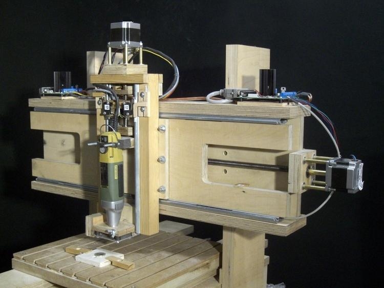

| Construction: | 20 and 30 mm plywood, glued, screwed and bolted |
| Linear guides: | X axis runs between 2 pairs of drawer guides, fixed end-to-end. |
| Y axis runs on 2 pairs of drawer guides, fixed end-to-end. | |
| Z axis runs between 2 drawer guides | |
| Lead screws: | M12 ISO threaded rod with nuts cut from Polyamid |
| Motors: | 400 step, NEMA 23, 1.7A stepping motors |
| Motor drivers: | Z axis: driver kit from Pollin Electronic with L297 chip, phase, 2A |
| X and Y axes refitted with ST330 boards: TB6560 chip, step/dir, 3.5A | |
| Couplings: | Z motor: brass tube. X and Y motors refitted with flexible DIY couplings. |
| Spindle: | Proxxon IB/E, max. speed: 20,000 RPM |
| Tools: | Proxxon 1 mm and 2 mm mills with 3 mm shafts |
Software |
|
| CAD: | QCad V.2.0.5.0 (RibbonSoft) |
| DXF to G-Code: | Ace V4.0 beta (DAK Engineering) |
| G-Code to plot: | Code editor and backplotter V.1.2 (NC Plot) |
| CNC: | TurboCNC for DOS V.4.01 (DAK Engineering) |
|
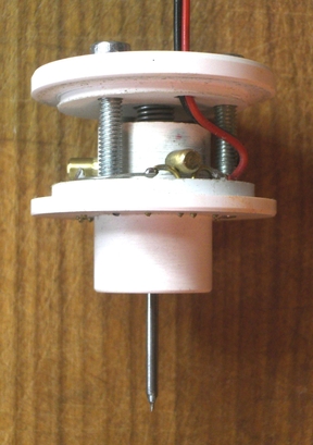
Touch probe details
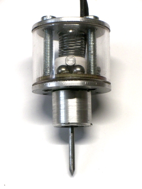
Based on a Renishaw probe. Briefly: each of the 3 brass prongs of the probe (two are visible) is pressed against a gap in a brass wire, by a spring - just visible in the centre. This completes a series circuit: +__o____o____o__- Operation: The probe is moved toward the object. When the probe touches, one of the contacts is opened, the circuit is broken and the current position of the probe is recorded. The probe is then backed away from the object and the circuit closes again. NB. The preferred material for the electrical contacts is hardened steel - not brass. |
|
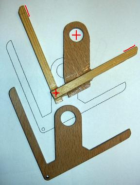
a 2D scan with the touch probe
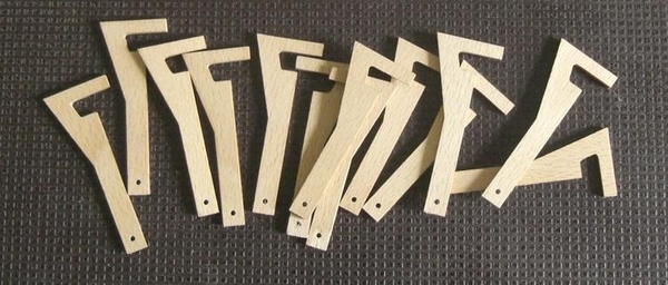
I used TurboCNC to scan a crudely-made, but finely-adjusted prototype part. It found the centres of the two holes and the positions of the two arms. and these dimensions formed the basis for a CAD drawing. The milling machine then cut out the finished part - the composer for a Harrison grasshopper clock escapement. |
|
a 3D scan with the touch probe
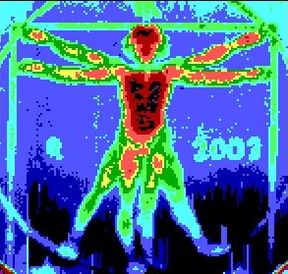
The Vitruvian Man on an Italian €1 coin rendered in 9 colours, like a relief map, using a short BASIC program. The measurements were made on a 0.1 mm grid. |
|
another way of looking at it
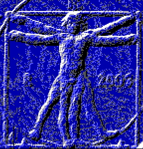
Here, the same 150 x 150 "point cloud" was rendered in a different way: comparing each height measurement with its north-westerly neighbour, noting the difference in their height and then shading its pixel, lighter or darker accordingly. A noisy image, but perhaps the best that can be expected from a touch probe with brass contacts. Some tweaking needed there. |
|
Two more touch probes I made
This one is of similar design to the one above but it has hard steel contacts rather than brass rods resting on bent wires. Also there are calibration grub screws under each of the contacts to make sure that the needle of the probe is exactly vertical.
during the 2021 covid lockdown |
|
Scanning a 2 Euro coin
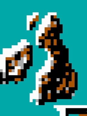
This is a scan of the British Isles on the reverse side of a 2 Euro coin. The image is 4mm high by 3 mm wide and it was probed every 0.1 mm - a total of 1200 measurments. It took about 20 minutes. The line on the south-east corner is the top of the letter "E" of the script "EURO" which runs from northern France to the Black Sea, obliterating many countries on its way. The map on this 2002 coin is rather schematic. Recent designs have more coastline detail. |
|
same data, different rendering
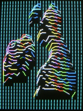
Here the heights of the coin are represented as succesive exaggerated profiles. For a serious application I would have left them in black and white but here they are in the colours that my TurboBasic program associates with these height numbers. The screen shot shows the entire height of the screen at medium screen resolution. For a higher resolution I would have to probe the coin at 0.01 millimeter intervals which, at one probe per second, would take more hours than I want to wait. The coin was clamped to a thick sheet of plexiglass. Having scanned the coin, I removed it and scanned the flat plexiglass surface beneath it. I subtracted this plexiglass data from the coin data to cancel out any inherent slope or local lumps and bumps in the operation of the machine. |
|
... the other touch probe
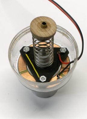
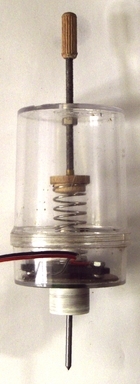
This probe differs from the Renishaw-style probes above. It is based on a design that is documented at diyercorner blogspot. It has just three contacts instead of six. Three screws rest on a ring of printed circuit board which is divided unequally into two sectors, one 240°, the other 120°. If you look at the photo carefully you can follow the series circuit that runs between the red and black wire terminals. If one of the three screws is lifted by the probe, the circuit is broken. I built it in one afternoon using a small plastic screw-top kitchen container. What you see in the photo is inside the lid. |
|
|
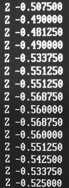
Since I had just one possible spring available and my spring supplier was closed during the covid lockdown, I made the pressure of the spring adjustable with a screw that emerges from what is now the top of the container. Here is the raw height data in millimeters. It is somewhat repetitive since the probe moves in jumps of 0.004375 mm. This is determined by the 1.75mm pitch of the 12mm lead screw and the 200 steps of the stepping motor that drives it. It could be improved by micro-stepping the motor. |
|
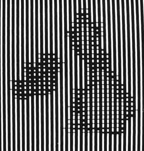
Another scan of the British Isles on a 2 Euro coin with the above probe from an original 3 x 3 mm image, measured every 0.1 mm..This 2018 minted coin has more coastline detail than my previous coins but the land is flat, without mountains, and rendered with a matte dimpled finish. The lower left corner of the image is at the exact centre of the coin. A 2-Euro-sized washer with a large hole was laid on top of the coin and the probe used its "find the centre of a hole program" to locate its starting position. |
|
|
Brush plot
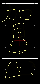
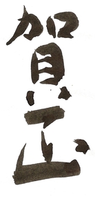
New Year's Greetings in Japanese. On the left is my original CAD drawing.
I then spent some of the time between Christmas and New Year adjusting the program until
it was able to produce something resembling my model (the small picture above.)
|
|
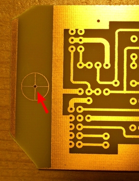
Drilling printed circuit boards
After I had etched some printed circuit boards, the machine drilled the holes.
|