This is about my weight-driven Synchronome.
It was inspired by the original
electro-mechanical Synchronome
The original Synchronome clock was invented by George Bennett Bowell in 1895 and developed and distributed by Frank Hope-Jones. Until the 1960s they were used as master clocks in large institutions and factories which required a precise timekeeper to control all the clocks on the premises.
  Once every 30 seconds the count wheel of the master clock releases a gravity arm which pushes the pendulum and sends an electrical pulse to move the hands of all the slave clocks. It also switches on two electro magnets that reset the gravity arm ready to give the next push.
  Synchronomes also served as slaves for the famous Shortt-Synchronome clocks which were the world's best timekeepers in the 1920s and 30s, installed in many observatories.
  These were the first clocks that were more precise than the rotations of the Earth itself. Since the 1940s they have been replaced by quartz clocks and later by atomic clocks. Recently, a Shortt-Synchronome under test has been found to have an error of one second in 12 years.
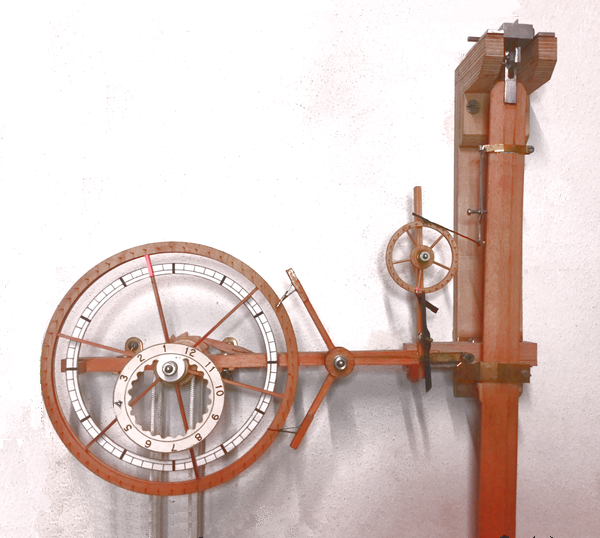
drawing of a Synchronome clock

My weight-driven version

photo of clock It is twelve, fifty-eight and thirty-two seconds.
Like the original Synchronome, the pendulum is powered by a gravity arm pushing down on a pallet but the rest of the mechanism is different. My version is driven by a weight whereas the Synchronome was powered by an electro-magnet.

Time keeping: My clock has an unvarnished wooden pendulum with a lead bob (weight 5.3 kg) swinging in an arc of 3° with a Q value of about 25,000. It keeps time to about one second from day to day but drifts with changes in humidity, temperature and atmospheric pressure. It is the most accurate clock I have made so far but might be improved by giving the pendulum rod a coat of yacht varnish or by replacing it with a carbon fibre or invar rod.

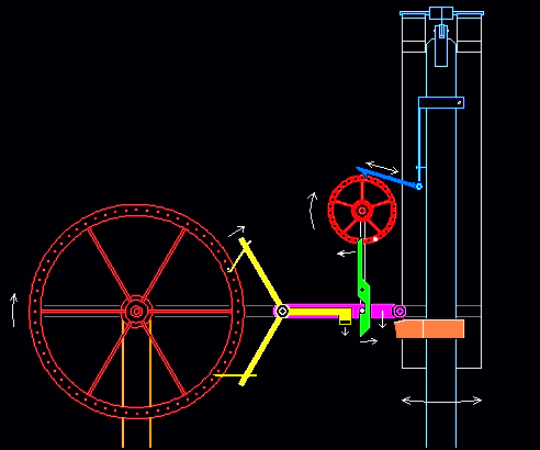
Once a minute the pendulum triggers the weight-driven mechanism.
The mechanism responds by giving the pendulum a push to keep it swinging.


  • The gathering arm attached to the pendulum turns the count wheel one pin every 2 seconds (on its swing to the right), one revolution a minute.
  • One pin (white dot) is longer than the rest. Once a minute, it touches the trigger releasing the gravity arm .
  • The gravity arm roller drops gently onto the pallet of the pendulum and falls off the pallet as it moves to the right, giving the pendulum an impulse.
  • The gravity arm then lands on the arm of the reset lever releasing a hook from a pin on the large hour wheel (left)
  • The hour wheel, driven by a weight on the cord, turns 1 step clockwise. As it turns it raises the reset lever which lifts the gravity arm.
  • The gravity arm is caught again by the trigger and held just clear of the pallet; ready to give the next impulse.
drawing of a clock

The count wheel was cut on a lathe

The rim and hub were turned from a disc of plywood glued to a scrap-wood faceplate held in the chuck of the lathe. The holes for the spokes, the pins and the original 8 x 5 mm ball-bearing were made with drills mounted on the tool-post. I used a strip of Ikea ½ millimeter tape wrapped around the chuck, and some arithmetic, as a dividing head. The spokes were fitted and the wheel was then cut free from the sacrificial faceplate.

They say that a count wheel mops up power and disturbs the pendulum so I changed the bearings and the pawl.

Following my exhibition at the Saarland Clock Museum I was kindly sent a packet of synthetic-ruby bearings and other precision clock components by master clock maker Erich Löhfelm. I replaced the ball-bearing of the count wheel with 4 ruby bearings turning on a 0.5 mm axle. The wheel now spins when blown on gently and the long pin required a counter-balance weight. The pendulum amplitude increased and I reduced the driving weight by 20%.

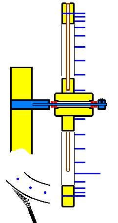
Bottom left. A soft brush of carbon fibers, trimmed as shown, replaced the previous pawl. It just touches the rim of the count wheel. The sloping wood fibres on the outside edge of the rim (it was turned clockwise!) engage with the fibres of the brush. This prevents the wheel from turning anti-clockwise - a precision low-friction ratchet on a microscopic scale.
detail drawing of count-wheel


Other wheel-making techniques, illustrated
Exhibition at a clock museum
picture of a spider
space